
Graphics Card Thermal Imaging Temperature Measurements
Thermal Imaging Temperature Measurements
A new addition to our reviews will be the inclusion of Forward Looking Infra Red thermal images of hardware. Over the past years we have been trying to figure out what the best possible way is to measure temperatures on hardware. Multiple options are available but the best thing to do is to visualize heat coming from the product or component being tested. The downside of thermal imaging hardware is simple, FLIR camera's with a bit of decent resolution costs up-to 10,000 EUR. Hence we passed on it for a long time. With a thermal imaging camera a special lens focuses the infrared light emitted by all of the objects in view. This focused light is scanned by a phased array of infrared-detector elements. The detector elements create a very detailed temperature pattern called a thermogram. It only takes about one-thirtieth of a second for the detector array to obtain the temperature information to make the thermogram. This information is obtained from several thousand points in the field of view of the detector array. The thermogram created by the detector elements is translated into electric impulses. The impulses are sent to a signal-processing unit, a circuit board with a dedicated chip that translates the information from the elements into data for the display. The signal-processing unit sends the information to the display, where it appears as various colors depending on the intensity of the infrared emission. The combination of all the impulses from all of the elements creates the image.
Why A Move Towards Thermal Imaging?
With thermal imaging we can seek hotspots on the PCB indicating, for example, GPU but also VRM temperature as well as how heat is distributed throughout a product. We do hope you will enjoy this new technology as it did cost us an arm and a leg to be able to implement it.
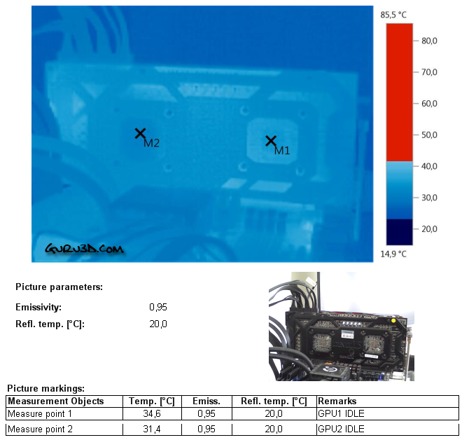
Above, you can see the graphics card in IDLE conditions. We position our measure point in the GPU die area at the backside of the PCB. Normal IDLE temperatures really. And it is fun to see that indeed one GPU disabled itself if Crossfire mode is not activated. You can see that the M1 GPU is active.
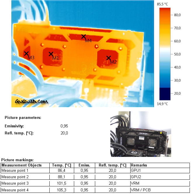
Once we start to stress the GPU the thermals quickly change. Now we can measure thermals into the 10th of a degree precise. You'll notice that the VRM zone at the M3/M4 position is running the hottest at over 100 degrees C, that is really bad. The GPU at M1 and M2 show temperatures in-between 85 to 90 Degrees C. These readings are very worrisome to be honest.
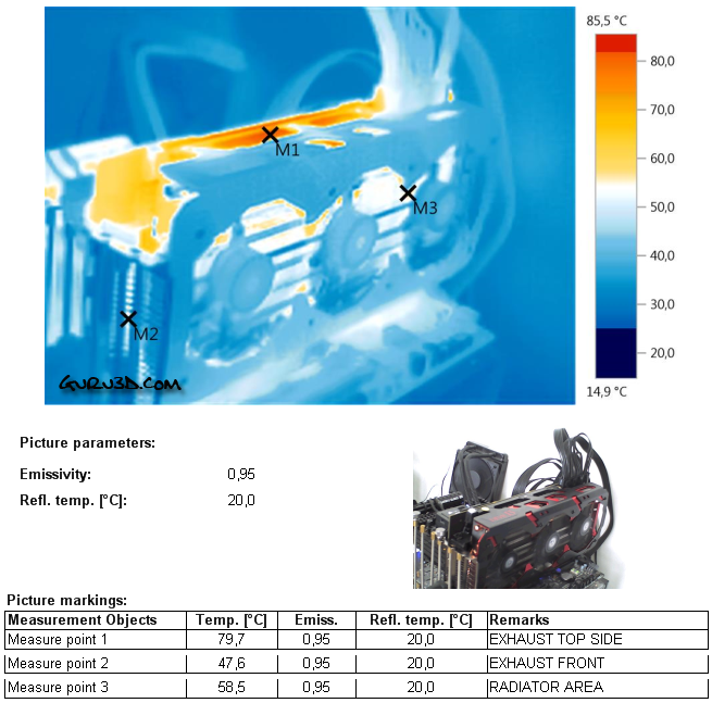
When we position the thermal camera outwards we can see that the hottest point obviously is the heatsink. There is very little heat to see/measure at the graphics card. The heatsink exhaust temperature is 60 Degrees C.
You'll notice that the top side is the hottest spot, unfortunately the tremendous amounts of heat are ditched for like 70% at the topside of the card. That means most heat will end up inside your PC and will not be exhausted well enough outside the PC.
