VRM Area Thermals
VRM Area Thermals
Lately it has been requested if we could list VRM temperatures. We could hook into sensors and start measuring. but the best way really is to look at the VRM area with a thermal camera. This way you can detect hot-spots and/or worrying stuff. We test:
- Normal conditions / default settings
- Overclocked processor at 4200 MHz All cores and ~1.44 Volts
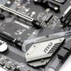
Default clock frequencies
Above a thermal image of the VRM Area and corresponding temperatures - this is under full CPU load and measured after 5 minutes in default conditions. M5 is the VRM heatsink under it, the MOSFETs, M2/M3 are the solid chokes and capacitors. There's nothing worrying to see here.
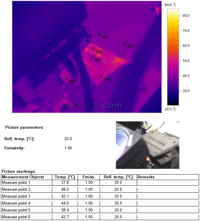
Overclock 4200 MHz / All core / 1.44V
Above a thermal image of the VRM Area and corresponding temperatures - this is under full CPU load and measured after 5 minutes in overclocked conditions. M1 is the VRM heatsink under it, the MOSFETs, M1 and the rest are the solid chokes and capacitors. Again, nothing worrying to see here. We did see one hotter spot, that that was an IC located at M6.
I do need to mention that the stock cooler is blowing air over this area. Ergo the dynamic would look different with say liquid cooling. But really, it is common sense that if you overclock that you at the very least account for sufficient airflow blowing over that VRM area.
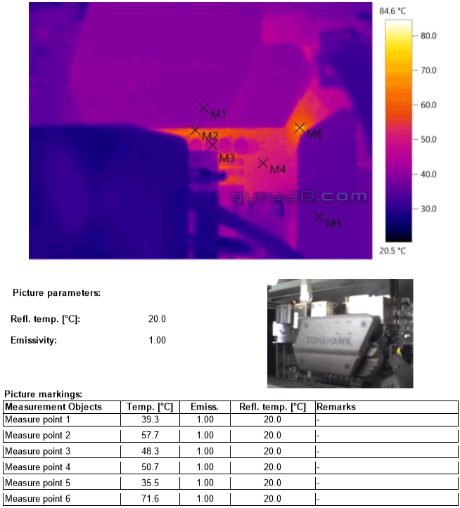
That IC, by the way, turned out to be the Dual-Channel multi-phase PWM Controller with I2C Interface that provides AMD the SVI2 CPU Power Supply (RT8894A).
