Page 7
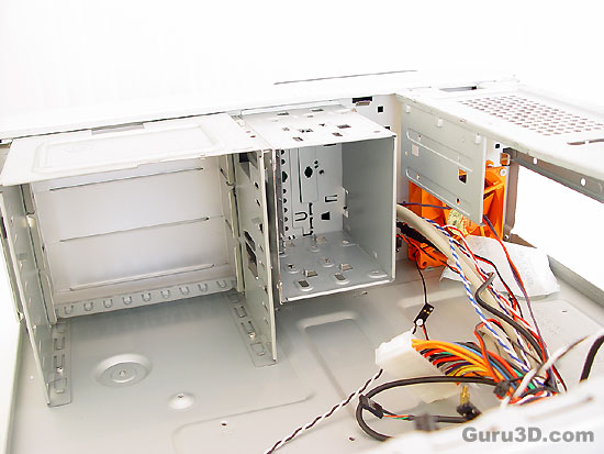
To your left you can see three 5.25" optical mounts, in the middle a three bay 3.5" drive cage that is held in place by three screws (can be removed) and on the duct to your right you can see 2 additional 3.5" spots for your HD's.
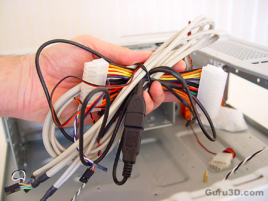
Now that's a bundle of cables. You use them to connect the front panel features to the motherboard installed. The cables are all of enough length, and features are well marked on the connectors to make things easier installation wise.
The VFD panel needs juice .. the wires simply power up the display. As you see, theres nothing unusual here: one ground, one +5V and one +5V standby voltage to power the display when the system is shut down. Yes you read it right, you can enable this system with your remote control.
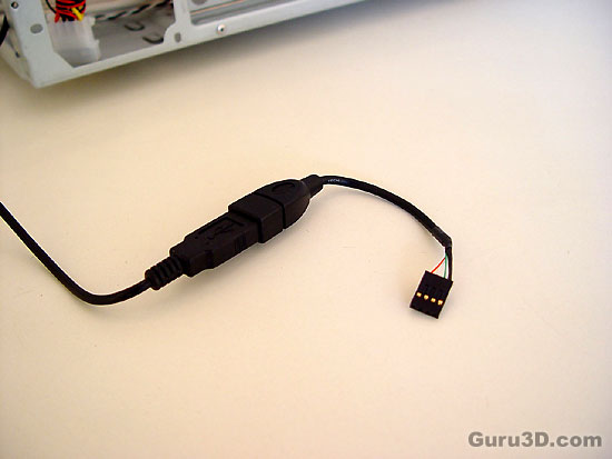
The model we test today comes with the flashy VFD display panel .. that means more wires inside. First, it is an interface cable for the display and IR sensor. It uses one universal USB connector. You can plug it into any free USB port on the rear panel or you can use a mainboards header.
