Product Innards
Product Innards
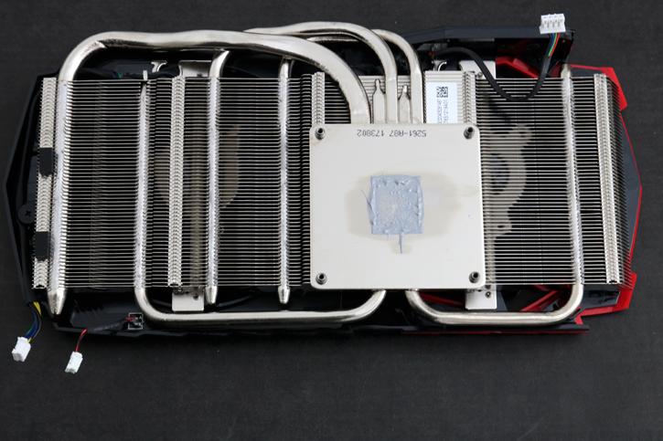
Those Twinfrozr coolers differ even in the same revision (V6) as can be seen here. Above the GeForce GTX 1070 Ti Gaming Twinfrozr VI cooler. Now look below:
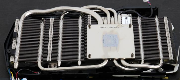
And above the Titanium cooler, as you can see there is one additional heat pipe. This doesn't have a real effect on cooling performance, the Titanium model we measured to be 1 Degree C lower in temp. The cooling solution is impressive overall, it uses heat-pipes that pass through a heatsink, with thermal paste tied to the all-copper yet nickel plated block. That's as good as it gets really, and sure, that shows in the great cooling performance.
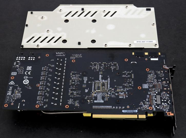
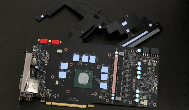
Here we take off the back-plate locked in with screws. At the top sits the RGB LED unit. As you can see the inside of the has enough spacing, regardless there is a nice plastic coating there, should for whatever reason a component ever hit the PCB, it would not short out. The Gaming and Titanium have 100% the same component and PCB usage.
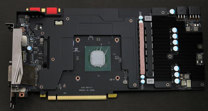
When we flip the PCB it around you can also see that the critical components are covered with a full contact plate, the memory is covered and has padding as well as the phase chokes and thus is cooled.
Again look how clean that PCB seems to be, very nice. With the cooler blocks removed, we now have the full PCB visible. This is a very clean PCB design alright. Let's run through some of the components. Critical components are covered and padded, The power stages have padding as well and thus is cooled as well as most ICs. We can now see the power stages, GPU, memory and voltage phase-controller.
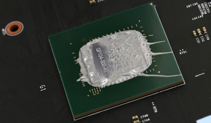
Here we have the GP104-300-A1 graphics processor from Nvidia with its 2,432 active CUDA / Shader Cores.
GDDR5 memory chips are made by Micron and are specced to run at 8,008 MHz GDDR5 (effective data-rate). Tweaked you are looking at a capability of roughly 8,600 ~ 9,000 MHz (effective data-rate).
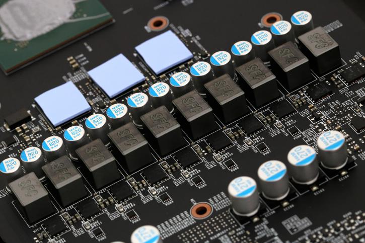
You can count them, 10 phases, eight for the GPU. We first stumble into capacitors, in the middle molded indicators (chokes). These concrete alloy chokes help to decrease buzzing noises. And then the square chips to the left are MOSFETs, DrMOS. The power phases are nicely cushioned with thermal padding reaching that cold-plate on the cooler.
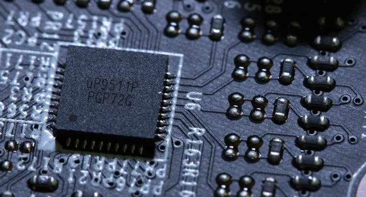
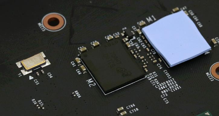
I had to change lighting and look and then look again. The photo reveals a UPI based uP9511P voltage regulator, a recent and much-used model voltage controller for many NVIDIA GP104 GPU based graphics cards. uP9511 can be configured in 8/7/6/5/4/3/2/1-phase operation and if you counted with me there are 8 of them + 2 for memory.
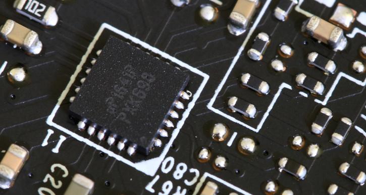
Phases - we still need two phases to memory, above a UPI Semiconductor uP1641 VRM controller which is capable of two phases. The 10 phase power of this card is 8+2 where 8 phases are used for the GPU and 2 phases are for the memory.
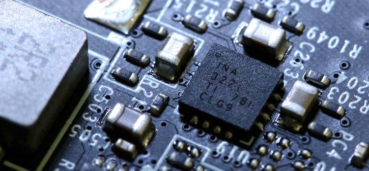
Current monitoring is enabled through a three-channel INA3221.
