Page 9
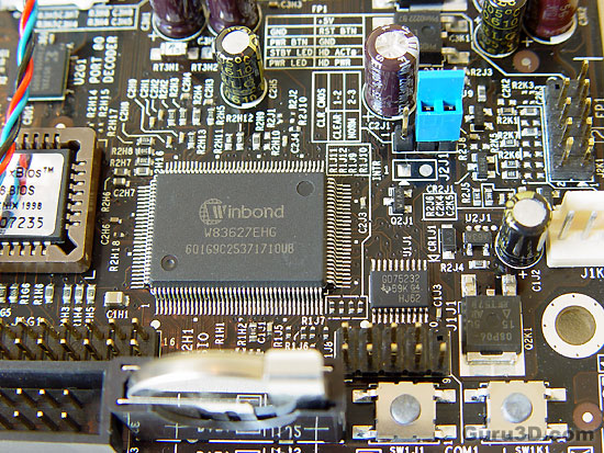
To your right, the 9 pins are for front panel connectivity like power-on, reset , HD LED etc etc. There's a clear description on the PCB yet they are not color coded. TBH this is not the way I like to see it done. To your lower right you can see two small switches. They control power on and reset. Really handy when you overclock a lot.
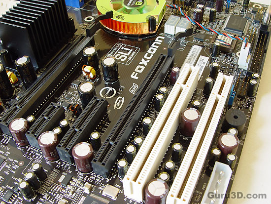
The available riser slots. The x16 PCI Express two slots are placed apart instead of one slot apart for better thermals when two cards are used in SLI mode. Furthermore a 1x and 4x PCIe slot with next to it 2x PCI slots.
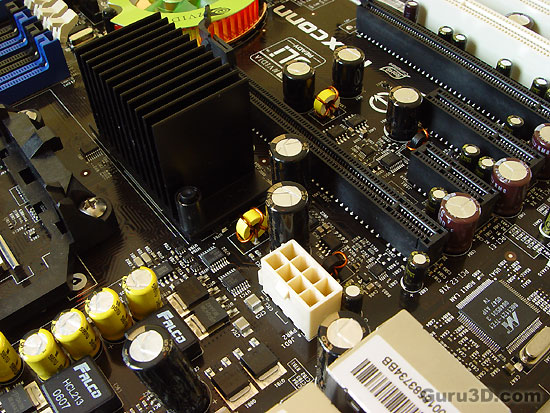
Here we can see the 2x4 12volts connector. Most newer PSU's have these already. If you don't .. do not worry. The 1x 4pin 12 volts connector will suffice also.
And a passively cooled Southbridge chip, the SPP. As you can see we are prepping the mainboard here to slowly get us where we want to be .. testing it!
