FLIR Thermal Images
Thermal Imaging Temperature Measurements
Over the past years we have been trying to figure out what the best possible way is to measure temperatures on hardware. Multiple options are available but the best thing to do is to visualize heat coming from the product or component being tested. The downside of thermal imaging hardware is simple, FLIR camera's with a bit of decent resolution costs up-to 10,000 EUR. Hence we passed on it for a long time. With a thermal imaging camera a special lens focuses the infrared light emitted by all of the objects in view. This focused light is scanned by a phased array of infrared-detector elements. The detector elements create a very detailed temperature pattern called a thermogram. It only takes about one-thirtieth of a second for the detector array to obtain the temperature information to make the thermogram. This information is obtained from several thousand points in the field of view of the detector array. The thermogram created by the detector elements is translated into electric impulses. The impulses are sent to a signal-processing unit, a circuit board with a dedicated chip that translates the information from the elements into data for the display. The signal-processing unit sends the information to the display, where it appears as various colors depending on the intensity of the infrared emission. The combination of all the impulses from all of the elements creates the image. We can seek hotspots on the PCB indicating, for example, CPU but also VRM temperature as well as how heat is distributed throughout a product.
First let me light up a regular stressed reference clocked Core i7 6700K on the 360P kit from EK. See above the processor under 100% stress. Thus that is the baseline 6700K. Our FLIR camera is setup to start lighting up at 20 Degrees C with a plafond set to 85 Degrees C. It's hardly even worth testing :)
Now let's look at the thermal image below:
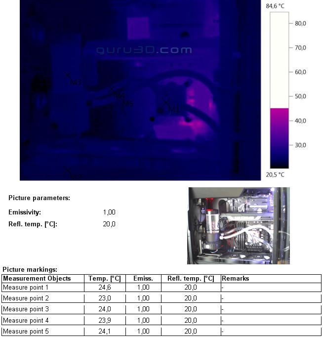
Here's the 6700K processor 100% stressed on CPUs (and FPUs as well btw) overclocked to 4600 MHz with 1.30 Volts.
- M1 is the CPU area showing roughly 24 Degrees C.
- M2 is the radiator showing 23 Degrees C
- M3 is the coolant in the reservoir
- M3 is your cooland tube inlet
- M4 is your coolant tube outlet
Again the cooling system doesn't even light up in the thermal image.

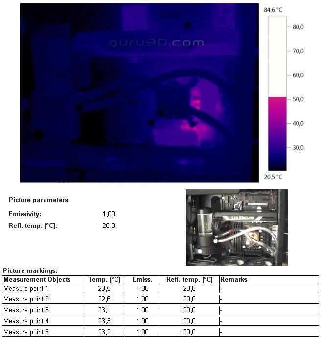
Finally - Heavily overclocked - here's the 6700K processor 100% stressed on CPUs and FPUs overclocked to 4600 MHz with a rather rediculous 1.50 Volts.
- M1 is the CPU area showing roughly 24 Degrees C.
- M2 is the radiator showing 24 Degrees C
- M3 is the coolant in the reservoir
- M3 is your cooland tube inlet
- M4 is your coolant tube outlet
Again the cooling system doesn't even light up in the thermal image. The 360P kit can easily take the heat, it's just that the heatspreader of the processor is internally causing things to heat up.

Here a close-up of the cooling block while the 6700K processor 100% stressed on CPUs and FPUs overclocked to 4600 MHz with 1.50 Volts. The only thing warm (not hot) is the VRM area of the motherboard at almost 60 Degrees C. Not bad, huh?
