Graphics Card Thermal Imaging Temperature Measurements
Thermal Imaging Temperature Measurements
A new addition towards our reviews will be the inclusion of Forward Looking Infra Red thermal images of hardware. Over the past years we have been trying to figure out what the best possible way is to measure temperatures on hardware. Multiple options are available but the best thing to do is to visualize heat coming from the product or component being tested. The downside of thermal imaging hardware is simple, FLIR camera's with a bit of decent resolution costs up-to 10,000 EUR. Hence we passed on it for a long time.
With a thermal imaging camera a special lens focuses the infrared light emitted by all of the objects in view. This focused light is scanned by a phased array of infrared-detector elements. The detector elements create a very detailed temperature pattern called a thermogram. It only takes about one-thirtieth of a second for the detector array to obtain the temperature information to make the thermogram. This information is obtained from several thousand points in the field of view of the detector array. The thermogram created by the detector elements is translated into electric impulses. The impulses are sent to a signal-processing unit, a circuit board with a dedicated chip that translates the information from the elements into data for the display. The signal-processing unit sends the information to the display, where it appears as various colors depending on the intensity of the infrared emission. The combination of all the impulses from all of the elements creates the image.
Why A Move Towards Thermal Imaging?
A new trend e.g. cheating is that manufacturers are tweaking their products with another offset, meaning that sometimes (and we have seen this only a couple of times) the temperature reported back by monitoring software often was lower then the product in reality is. With thermal imaging this becomes this becomes a thing of the past as we can seek hotspots on the PCB indicating for example GPU but also VRM temperature as well as how heat is distributed throughout a product. We do hope you will enjoy this new technology as it did cost us an arm and a leg to be able to implement it.
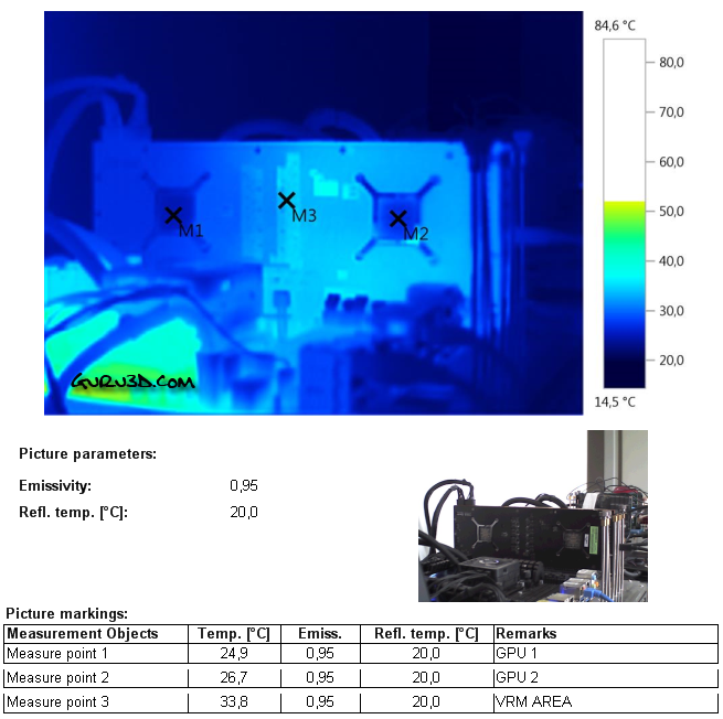
Above you can see the graphics card in IDLE conditions. We position our measure point in the GPU die area at the backside of the PCB. Excellent IDLE temperatures really.
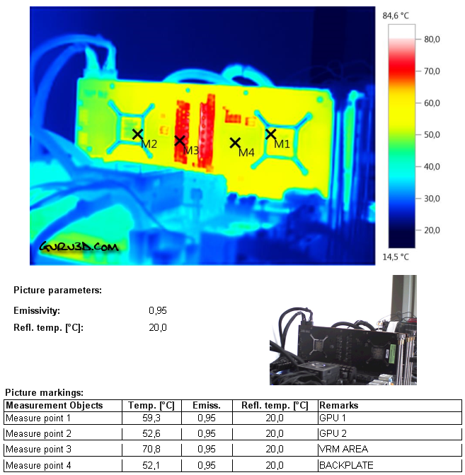
Once we start to stress the GPU the thermals quickly change. Now we can measure thermals into the 10th of a degree precise. You'll notice that the VRM zone at the M3 position is running the hottest at almost 71 degrees C, that is really good. The GPU at M1 and M2 show downright good temperatures.
We can't measure GPU heat due to the closed backplate.
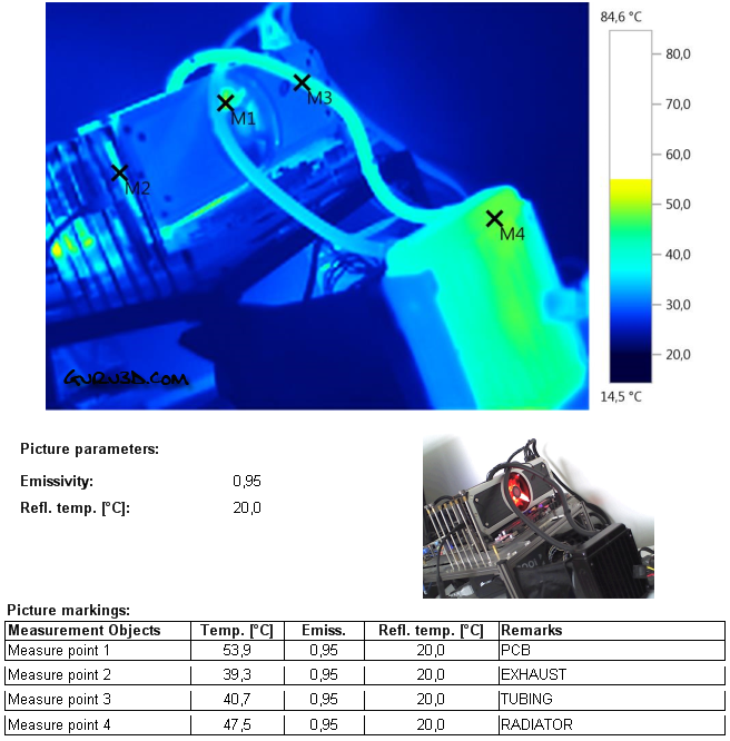
When we position the thermal camera outwards we can see that the hottest point obviously is the radiator. There is very little heat to see/measure at the graphics card. The radiator exhaust temperature is 48 Degrees C. Overall, I am happy with the results and it shows that the hybrid cooling really is efficient enough to cool down what probably is the hottest product on the globe. Mind you though, inside a PC you will need PROPER ventilation due to the nature of liquid cooling.
