Product Gallery - the ASUS Rampage III Extreme
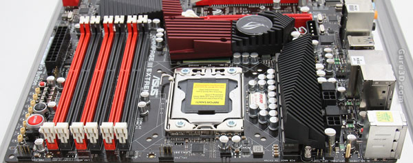
When we flip the board around we stumble into the processor area. We spot two 8-pin CPU power header located well (right to the heatsink), all ferrite core chokes and quality capacitors catch the eye. And obviously there's Socket 1366.
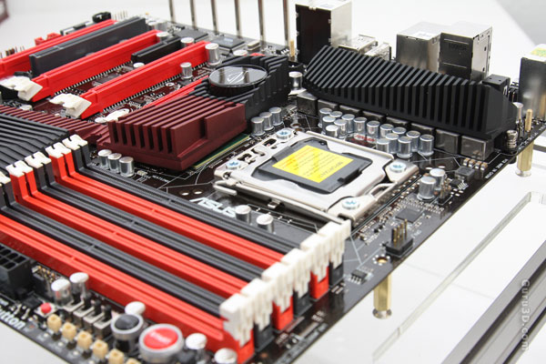
Also we spot lower RDS MOSFETs and lower ESR solid capacitors are used here. Pure quality components are being used and nothing else. We see that the board design is completely passively cooled.
The boards phase design is as follows:
-
eight phases on the CPU
-
three phases for QPI/DRAM power
-
three phases for PCH (x58)
-
three phases for memory
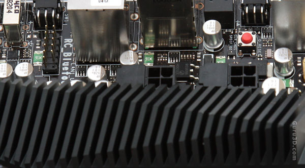
Here you can see the two eight-pin CPU power headers with above it a Q-reset button. Extreme overclockers may sometimes face the hard decision between whether they should reset or force power down the system when the extreme overclocked rig half once in a while, as the press of reset button does not always work, while force power down may often result in freezing the components under S5 mode. This is where Q Reset comes in.
The Q Reset button at the top left hand corner of the board allows users to clear CMOS then power up in a flash to bypasses S5 mode to avoid the need to face either of these limitations.
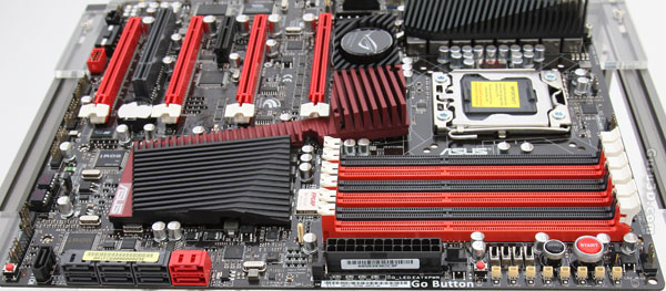
Once we flip the board around we stumble into the DIMM slots, DDR3 of course. Up-to 24GB may be installed and the board will actually support 2200 MHz straight out of the BIOS (though overclocked). XMP profiles are detected properly and if desired activated optionally. What you'll notice is that everything is just positioned really well. But let's zoom in a little.
